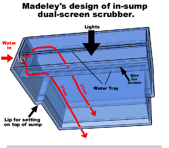
Madeley on the scrubber site has come up with a great plan for an in-sump dual-screen scrubber, that could either be manufactured from plastic, or (if you simplify it) made out of acrylic. So for you technically adept folks, here's his drawing, with my arrows and words added:
His drawing is similar to Dohn's on the MASA site:
http://www.radio-media.com/fish/UserDohnOnMASA-2.jpg
...but simpler (Dohn's I believe was for HOB, so it's understandably more complex).
Operation: Madeley has it so it can be placed in a sump front-to-back (sump being sideways), and it will set on the rim; lights in the middle, screens on both sides through the slots in the horizontal water tray, and water fed in from the hole on the end which would thus be positioned at the back or front of the sump. If it's for a sump 12" front-to-back, then the lower section is probably 11" across, which makes the screen about 10" across. So if the screen is 10" tall, then it's 100 square inches, and lit on one side, which is good for a 50 gal tank per screen, or 100 gal tank total. Each 10" wide screen needs 10 X 35 = 350 gph flow, for a total of 700 gph. Lighting could either be two CFL's hung down the middle, or some type of two-sided T5HO (just think how powerful a row of ten 12" T5's would be. This could be an optional feature.)
To mold/manufacture out of plastic, here's what I'd change:
1. Water input-hole: Many sumps I've seen won't have room to route a tube/pipe along the back side of their sumps (in order to connect to that hole), and they'd prefer to not route it in from the front. I'd suggest a side or top connection.
2. The incoming 700 gph water, the way is is laid out, is going to be too strong when it hits that center piece. I'd use two separate holes, and let the user divide the water himself with a "Y" before the input. Also, if you make the two water pathways totally isolated, and if the user puts a valve on each water input, then he can keep the pump running on one screen while he turns off and cleans the other. This is a safety factor because some people forget to turn their pumps back on, and/or, they are feeding the scrubber from the overflow. Also, there would be a perceived advantage because "it never stops filtering, even when I'm cleaning it".

3. Screen slots: If the screen inserts through the water tray from the top, then how do you get it out when it's full? You can't pull it up through the slot when it's full. And if the screen inserts from the bottom, how do you push it up and get it through the slot when the screen is flexible?. What you could do is make the water tray removeable, so it just sets down in there. This way, the tray would lift up and bring the screen with it (would also make cleaning, and manufacturing, easier.) And, you'd want the tray to be in two pieces so you can remove one without needing to remove the other. This would work great with isolated water pathways.
4. Overflowing tray: If something real or imaginary blocks the water from going down the slot, the user needs to know that the water will simply overflow into the sump. This is easily done by lowering the outer walls a half inch or so, in the middle section, so water would spill over the edge.
5. Top heavy: With water in the top tray, and two hoses connected, and lights attached, the cener of gravity is going to be very high, and the unit could tip over. While you could fix this by making the unit sit lower into the sump, this would reduce screen area since more of the screen would be under water. A solution might be to attach weights (rock?) to the bottom.
6. Adjustable height: Due to the top-heavy problem, and the unknown height of water in the user's sump, and also due to manufacturing difficulties, it might be easier to eliminate the ledge (that sits on the sump's rim) entirely, and replace it with an adjustable "lip" or "tab". This adjustable piece would be on both ends, and could be moved up or down so that the screen's bottom could be positioned just at the water's surface. If top-heavy, the unit could be lowered (albeit putting the screen into the water.)
An alternate solution to the height issue is to have no lip at all (permanent or adjustable), and instead use some type of legs that go down to the bottom of the sump. This would make the top part of the unit smaller (does not need to set on sump rim), but would not reduce the lighting or screen areas. For balance in top-heavy situations, the legs could be weighted (they could be weights themselves), or they could extend out at an angle like a tripod.
To have it built from acrylic instead (by hand), here's what I'd change:
The above points still apply (water input on top or side, dual inputs, separate water pathways, removeable water trays, lowered-wall to handle overflow). The issue with acrylic is to use as many long straight pieces as possible, and to avoid any internal cross sections. This pretty much eliminates the lip that would sit on the sump's rim, so something would have to hold the unit up; either an adjustable lip on the sides, or legs on the bottom. An easy solution might be to just extend the outer sheets of acrylic (the ones parallel to the screen) all the way to the bottom, and just have slots in them (like vertical window blinds) for water to get through. If made for anyone other than yourself (in which case you would not know the height needed), the user could just cut off the excess acrylic in order to set the height properly.
The acrylic design is very simple; just four vertical acrylic sheets (same size), with two end pieces, a drop-in water tray on both sides, and a water hole on both sides.
.


